Single line diagram or One-line diagram
Electric power systems are supplied by three-phase generators. Ideally, the generators are supplying balanced three phase loads. Fig.1.1 shows a star connected generator supplying star connected balanced load.
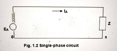
A balanced three-phase system is always solved as a single-phase circuit composed of one of the three lines and the neutral return. Single-phase circuit of three-phase system considered above is shown in Fig. 1.2.
Often the diagram is simplified further by omitting the neutral and by indicating the component parts by standard symbols rather than by their equivalent circuits. Such a simplified diagram of electric system is called a one-line diagram. It is also called as
single line diagram.
This system has two generators, one solidly grounded and the other grounded through a resistor, that are connected to a bus and through a step-up transformer to a transmission line. Another generator, grounded through a reactor, is connected to a bus and through a transformer to the other end of the transmission line. A load is connected to each bus.
On the one-line diagram information about the loads, the ratings of the generators and transformers, and reactances of different components of the circuit is often given.
Impedance and reactance diagram
In order to calculate the performance of a power system under load condition or upon the occurrence of a fault, the one line diagram is used to draw the single-phase or per phase equivalent circuit of the system.
Refer the one-line diagram of a sample power system shown below.
The impedance diagram does not include the current limiting impedances shown in the one-line diagram because no current flows in the ground under balanced condition.
Per-phase impedance diagram
per phase reactance diagram


No comments:
Post a Comment