adunit2

Thursday, May 27, 2021

FORMATION OF BUS IMPEDANCE MATRIX USING BUILDING ALGORITHM OR STEP BY STEP PROCEDURE OF FINDING BUS IMPEDANCE MATRIX Z BUS

 ZBUS building


FORMATION OF BUS IMPEDANCE MATRIX


The bus impedance matrix is the inverse of the bus admittance matrix. An alternative method is possible, based on an algorithm to form the bus impedance matrix directly from system parameters and the coded bus numbers. The bus impedance matrix is formed adding one element at a time to a partial network of the given system. The performance equation of the network in bus frame of reference in impedance form using the currents as independent variables is given in matrix form by


Now assume that the bus impedance matrix Zbus is known for a partial network of m buses and a known reference bus. Thus, Zbus of the partial network is of dimension mxm. If now a new element is added between buses p and q we have the following two possibilities:

(i) p is an existing bus in the partial network and q is a new bus; in this case p-q is a

branch added to the p-network as shown in Fig 1a, and


(ii) both p and q are buses existing in the partial network; in this case p-q is a link

added to the p-network as shown in Fig 1b.


If the added element ia a branch, p-q, then the new bus impedance matrix would be of order m+1, and the analysis is confined to finding only the elements of the new row and column (corresponding to bus-q) introduced into the original matrix. If the added element ia a link, p-q, then the new bus impedance matrix will remain unaltered with regard to its order. However, all the elements of the original matrix are updated to take account of the effect of the link added.

Wednesday, May 26, 2021

FORMATION OF BUS IMPEDANCE MATRIX ZBUS USING NODE ELIMINATION METHOD

 FORMATION OF BUS IMPEDANCE MATRIX

NODE ELIMINATION BY MATRIX ALGEBRA


Nodes can be eliminated by the matrix manipulation of the standard node equations. However, only those nodes at which current does not enter or leave the network can be considered for such elimination. Such nodes can be eliminated either in one group or by taking the eligible nodes one after the other for elimination, as discussed next.


CASE-A: Simultaneous Elimination of Nodes:


Consider the performance equation of the given network in bus frame of reference in admittance form for a n-bus system, given by:


IBUS = YBUS EBUS (1)


Where IBUS and EBUS are n-vectors of injected bus current and bus voltages and YBUS is the square, symmetric, coefficient bus admittance matrix of order n. Now, of the n buses present in the system, let p buses be considered for node elimination so that the reduced system after elimination of p nodes would be retained with m (= n-p) nodes only. Hence the corresponding performance equation would be similar to (1) except that the coefficient matrix would be of order m now, i.e.,


IBUS = YBUSnew EBUS (2)


Where YBUSnew is the bus admittance matrix of the reduced network and the vectors


IBUS and EBUS are of order m. It is assumed in (1) that IBUS and EBUS are obtained with their elements arranged such that the elements associated with p nodes to be eliminated are in the lower portion of the vectors. Then the elements of YBUS also get located accordingly so that (1) after matrix partitioning yields,


Where the self and mutual values of YA and YD are those identified only with the nodes to be retained and removed respectively and YC=YBt is composed of only the corresponding mutual admittance values, that are common to the nodes m and p.

Now, for the p nodes to be eliminated, it is necessary that, each element of the vector IBUS-p should be zero. Thus we have from (3):


IBUS-m = YA EBUS-m + YB EBUS-p IBUS-p = YC EBUS-m + YD EBUS-p = 0

(4)


Solving,

EBUS-p = - YD-1YC EBUS-m (5)

Thus, by simplification, we obtain an expression similar to (2) as,

IBUS-m = {YA - YBYD-1YC} EBUS-m (6)

Thus by comparing (2) and (6), we get an expression for the new bus admittance matrix in terms of the sub-matrices of the original bus admittance matrix as:

YBUSnew = {YA – YBYD -1YC} (7)

This expression enables us to construct the given network with only the necessary nodes retained and all the unwanted nodes/buses eliminated. However, it can be observed from

(7) that the expression involves finding the inverse of the sub-matrix YD (of order p). This would be computationally very tedious if p, the nodes to be eliminated is very large, especially for real practical systems. In such cases, it is more advantageous to eliminate the unwanted nodes from the given network by considering one node only at a time for elimination, as discussed next.


CASE-B: Separate Elimination of Nodes:

Here again, the system buses are to be renumbered, if necessary, such that the node to be removed always happens to be the last numbered one. The sub-matrix YD then would be a single element matrix and hence it inverse would be just equal to its own reciprocal value. Thus the generalized algorithmic equation for finding the elements of the new bus admittance matrix can be obtained from (6) as,


Yij new = Yij old – Yin Ynj / Ynn " i,j = 1,2,…… n. (8)


Each element of the original matrix must therefore be modified as per (7). Further, this procedure of eliminating the last numbered node from the given system of n nodes is to be iteratively repeated p times, so as to eliminate all the unnecessary p nodes from the original system.


POWER SYSTEM ANALYSIS, DETERMINATION OF BUS ADMITTANCE MATRIX USING SINGULAR TRANSFORMATION METHOD

 SINGULAR TRANSFORMATIONS


The primitive network matrices are the most basic matrices and depend purely on the impedance or admittance of the individual elements. However, they do not contain any information about the behaviour of the interconnected network variables. Hence, it is necessary to transform the primitive matrices into more meaningful matrices which can relate variables of the interconnected network.


Bus admittance matrix, YBUS and Bus impedance matrix, ZBUS


In the bus frame of reference, the performance of the interconnected network is described by n independent nodal equations, where n is the total number of buses (n+1nodes are present, out of which one of them is designated as the reference node).

For example a 5-bus system will have 5 external buses and 1 ground/ ref. bus). The performance equation relating the bus voltages to bus current injections in bus frame of reference in admittance form is given by


IBUS = YBUS EBUS

Where EBUS = vector of bus voltages measured with respect to reference bus IBUS = Vector of currents injected into the bus

YBUS = bus admittance matrix

The performance equation of the primitive network in admittance form is given by i + j = [y] v

Pre-multiplying by At (transpose of A), we obtain


At i +At j = At [y] v

However, as per equation 


At i =0,

since it indicates a vector whose elements are the algebraic sum of element currents incident at a bus, which by Kirchhoff‟s law is zero. Similarly, At j gives the algebraic sum of all source currents incident at each bus and this is nothing but the total current injected at the bus. Hence,


At j = IBUS

Thus  we have, IBUS = At [y] v

However,  we have v =A EBUS

And hence substituting in  we get,


IBUS = At [y] A EBUS

Comparing  we obtain,


YBUS = At [y] A

The bus incidence matrix is rectangular and hence singular. Hence, (22) gives a singular transformation of the primitive admittance matrix [y]. The bus impedance matrix is given by ,


ZBUS = YBUS-1

Note: This transformation can be derived using the concept of power invariance, however, since the transformations are based purely on KCL and KVL, the transformation will obviously be power invariant.


FORMATION OF BUS ADMITTANCE MATRIX ,Y BUS, METHODS TO DETERMINE YBUS, EXAMPLES

 FORMATION OF YBUS

The bus admittance matrix, YBUS plays a very important role in computer aided power system analysis. It can be formed in practice by either of the methods as under:

1. Rule of Inspection

2. Singular Transformation

3. Non-Singular Transformation

4. ZBUS Building Algorithms, etc.

Rule of Inspection


Consider the 3-node admittance network as shown in figure5. Using the basic branch relation: I = (YV), for all the elemental currents and applying Kirchhoff‟s Current Law principle at the nodal points, we get the relations as under:


At node 1: I1 =Y1V1 + Y3 (V1-V3) + Y6 (V1 – V2) At node 2: I2 =Y2V2 + Y5 (V2-V3) + Y6 (V2 – V1)

At node 3: 0 = Y3 (V3-V1) + Y4V3 + Y5 (V3 – V2)

In other words, the relation of equation (9) can be represented in the form

IBUS = YBUS EBUS                                                                                   

Where, YBUS is the bus admittance matrix, IBUS & EBUS are the bus current and bus voltage vectors respectively. By observing the elements of the bus admittance matrix, YBUS of equation (13), it is observed that the matrix elements can as well be obtained by a simple inspection of the given system diagram:

Diagonal elements: A diagonal element (Yii) of the bus admittance matrix, YBUS, is equal to the sum total of the admittance values of all the elements incident at the bus/node i,

Off Diagonal elements: An off-diagonal element (Yij) of the bus admittance matrix, YBUS, is equal to the negative of the admittance value of the connecting element present between the buses I and j, if any. This is the principle of the rule of inspection. Thus the algorithmic equations for the rule of inspection are obtained as:


Yii = S yij (j = 1,2,…….n)

Yij = - yij (j = 1,2,…….n)                                                                           

For i = 1,2,….n, n = no. of buses of the given system, yij is the admittance of element connected between buses i and j and yii is the admittance of element connected between bus i and ground (reference bus).


Bus impedance matrix

In cases where, the bus impedance matrix is also required, it cannot be formed by direct inspection of the given system diagram. However, the bus admittance matrix determined by the rule of inspection following the steps explained above, can be inverted to obtain the bus impedance matrix, since the two matrices are inter-invertible.


Tuesday, May 25, 2021

singular transformation method, power system analysis

 SINGULAR TRANSFORMATIONS


The primitive network matrices are the most basic matrices and depend purely on the impedance or admittance of the individual elements. However, they do not contain any


information about the behaviour of the interconnected network variables. Hence, it is necessary to transform the primitive matrices into more meaningful matrices which can relate variables of the interconnected network.

Bus admittance matrix, YBUS and Bus impedance matrix, ZBUS


In the bus frame of reference, the performance of the interconnected network is described by n independent nodal equations, where n is the total number of buses (n+1) nodes are present, out of which one of them is designated as the reference node). For example a 5-bus system will have 5 external buses and 1 ground/ ref. bus). The performance equation relating the bus voltages to bus current injections in bus frame of reference in admittance form is given by

IBUS = YBUS EBUS


where


EBUS = vector of bus voltages measured with respect to reference bus IBUS = Vector of currents injected into the bus

YBUS = bus admittance matrix


The performance equation of the primitive network in admittance form is given by


i + j = [y] v Pre-multiplying by At (transpose of A), we obtain

A t i +At j = At [y] v


However, A t i =0


Since it indicates a vector whose elements are the algebraic sum of element currents incident at a bus, which by Kirchhoff’s law is zero. Similarly, At j gives the algebraic sum of all source currents incident at each bus and this is nothing but the total current injected at the bus. Hence, A t j = IBUS

Thus we have, IBUS = At [y] v


v =A EBUS

IBUS = At [y] A EBUS YBUS = At [y] A


The bus incidence matrix is rectangular and hence singular. Hence, the above equation gives a singular transformation of the primitive admittance matrix [y]. The bus impedance matrix is given by ,

ZBUS = YBUS-1

Note: This transformation can be derived using the concept of power invariance, however, since the transformations are based purely on KCL and KVL, the transformation will obviously be power invariant.


Monday, May 24, 2021

PRIMITIVE NETWORK AND BUS ADMITTANCE MATRIX

 Primitive network matrices

 A diagonal element in the matrices, [z] or [y] is the self impedance zpq-pq or self admittance, ypq-pq. An off-diagonal element is the mutual impedance, zpq-rs or mutual admittance, ypq-rs, the value present as a mutual coupling between the elements p-q and r-s. The primitive network admittance matrix, [y] can be obtained also by inverting the primitive impedance matrix, [z]. Further, if there are no mutually coupled elements in the given system, then both the matrices, [z] and [y] are diagonal. In such cases, the self impedances are just equal to the reciprocal of the corresponding values of self admittances, and vice-versa.

Bus Admittance Matrix


Bus admittance matrix (YBus) for an n-bus power system is square matrix of size n × n. The diagonal elements represent the self or short circuit driving point admittances with respect to each bus. The off-diagonal elements are the short circuit transfer admittances (or) the admittances common between any two number of buses. In other words, the diagonal element yii of the YBus is the total admittance value with respect to the ith bus and yik is the value of the admittance that is present between ith and kth buses. YBus can be obtained by the following methods:

1. Direct inspection method


2. Step-by-step procedure


3. Singular transformation


4. Non-singular transformation


Direct inspection method


Formulation of YBus by direct inspection method is suitable for the small size networks. In this method the YBus matrix is developed simply by inspecting structure of the network without developing any kind of equations. Let us consider a 3-bus power system shown in figure below:


Since [B]T * i is zero because, algebraic sum of all the currents meeting at a node is zero. The source current matrix [j] can be partitioned into,


PRIMITIVE NETWORK REPRESENTATION, IN IMPEDANCE FORM AND ADMITTANCE FORM

 PRIMITIVE NETWORKS


So far, the matrices of the interconnected network have been defined. These matrices contain complete information about the network connectivity, the orientation of current, the loops and cut sets. However, these matrices contain no information on the nature of the elements which form the interconnected network. The complete behaviour of the network can be obtained from the knowledge of the behaviour of the individual elements which make the network, along with the incidence matrices. An element in an electrical network is completely characterized by the relationship between the current through the element and the voltage across it.


General representation of a network element: In general, a network element may contain active or passive components. Figure 2 represents the alternative impedance and admittance forms of representation of a general network component.


The network performance can be represented by using either the impedance or the admittance form of representation. With respect to the element, p-q, let,

vpq = voltage across the element p-q,
epq = source voltage in series with the element pq, ipq= current through the element p-q,
jpq= source current in shunt with the element pq, zpq= self impedance of the element p-q and
ypq= self admittance of the element p-q.

Performance equation: Each element p-q has two variables, vpq and ipq. The performance of the given element p-q can be expressed by the performance equations as under:

vpq + epq = zpqipq (in its impedance form) ipq + jpq = ypqvpq (in its admittance form)
Thus the parallel source current jpq in admittance form can be related to the series source voltage, epq in impedance form as per the identity:
 
jpq = - ypq epq

A set of non-connected elements of a given system is defined as a primitive Network and an element in it is a fundamental element that is not connected to any other element. In the equations above, if the variables and parameters are replaced by the corresponding vectors and matrices, referring to the complete set of elements present in a given system, then, we get the performance equations of the primitive network in the form as under:
v + e = [z] i i + j = [y] v


graph theory, incidance matrix, complete incidance matrix, reduced incidance matrix

 Graph Theory

Graph theory is the branch of mathematics dealing with graphs. In network analysis, graphs are used extensively to represent a network being analyzed. The graph of a network captures only certain aspects of a network; those aspects related to its connectivity, or, in other words, its topology.

Incidence matrix:


Any oriented graph can be described completely in a compact matrix form. Here we specify the orientation of each branch in the graph and the nodes at which this branch is incident. This branch is called incident matrix. When one row is completely deleted from the matrix the remaining matrix is called a reduced incidence matrix.

The rows of the matrix represent the nodes and the columns represent the branches of the graph.

i. The elements of the incidence matrix will be +1, -1 or zero.

ii. If a branch is connected to a node and its orientation is away from the node the corresponding element is marked +1.

iii. If a branch is connected to a node and its orientation is towards the node then the corresponding element is marked – 1.

iv. If a branch is not connected to a given node then the corresponding element is marked zero.

Incidance matrices are classified into two types.
1. Complete Incidence Matrix
2. Reduced Incidence Matrix

Complete incidence matrix:


An incidence matrix in which the summation of elements in any column is zero is called a complete incidence matrix.
 
It is an N × B matrix with elements of
 

An = [akj]
 
akj = 1, when the branch bj is incident to and oriented away from the kth node.
= −1, when the branch bj is incident to and oriented towards the kth node.
= 0, when the branch bj is not incident to the kth node. As each branch of the graph is incident to exactly two nodes,
n
Σ akj = 0
k=0
That is, each column of An has exactly two non zero elements, one being +1 and the other −1. Sum of elements of any column is zero. The columns of An are linearly dependent. The rank of the matrix is less than N.
Significance of the incidence matrix lies in the fact that it translates all the geometrical features in the graph into an algebraic expression.
Using the incidence matrix, we can write KCL as
An ∗ ib = 0,
Where ib =branch current vector.
But these equations are not linearly independent. The rank of the matrix An is N − 1. This property of An is used to define another matrix called reduced incidence matrix or bus incidence matrix.

Reduced incidence matrix:


The reduced incidence matrix is obtained from a complete incidence matrix by eliminating a row. Hence the summation of elements in any column is not zero.
Any node of a connected graph can be selected as a reference node. Then the voltages of the other nodes (referred to as buses) can be measured with respect to the assigned reference. The matrix obtained from An by deleting the row corresponding to the reference
 
node is the element bus incident matrix A and is called bus incidence matrix with dimension (N − 1) × B. A is rectangular and therefore singular.
From A, we have A ∗ ib = 0, which represents a set of linearly independent equations and there are N − 1 independent node equations.
For the graph shown in Fig 2.3(a), with d selected as the reference node, the reduced incidence matrix is


single line or one line diagram of power system, and impedance and reactance diagrams


Single line diagram or One-line diagram


Electric power systems are supplied by three-phase generators. Ideally, the generators are supplying balanced three phase loads. Fig.1.1 shows a star connected generator supplying star connected balanced load.

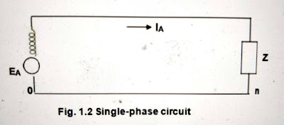
A balanced three-phase system is always solved as a single-phase circuit composed of one of the three lines and the neutral return. Single-phase circuit of three-phase system considered above is shown in Fig. 1.2.


Often the diagram is simplified further by omitting the neutral and by indicating the component parts by standard symbols rather than by their equivalent circuits. Such a simplified diagram of electric system is called a one-line diagram. It is also called as
single line diagram. 

This system has two generators, one solidly grounded and the other grounded through a resistor, that are connected to a bus and through a step-up transformer to a transmission line. Another generator, grounded through a reactor, is connected to a bus and through a transformer to the other end of the transmission line. A load is connected to each bus.
On the one-line diagram information about the loads, the ratings of the generators and transformers, and reactances of different components of the circuit is often given.

Impedance and reactance diagram


In order to calculate the performance of a power system under load condition or upon the occurrence of a fault, the one line diagram is used to draw the single-phase or per phase equivalent circuit of the system.
Refer the one-line diagram of a sample power system shown below.

The impedance diagram does not include the current limiting impedances shown in the one-line diagram because no current flows in the ground under balanced condition.


Per-phase impedance diagram


 per phase reactance diagram


per unit representation, formula, per unit representation of system

 PER UNIT REPRESENTATION & TOPOLOGY

Per Unit (pu) System

In power system analysis, it is common practice to use per-unit quantities for analyzing and communicating voltage, current, power, and impedance values. These per-unit quantities are normalized or scaled on a selected base, as shown in the equation below, allowing engineers to simplify power system calculations with multiple voltage transformations

per unit quantity = actual quantity/ base quantity


Historically, per-unit values have made power calculations performed by hand much simpler. With many calculations now being done using computer software, this is no longer the primary advantage; however, some advantages still exist. For example, when analyzing voltage on a larger system scale with many different nominal voltages via step-up and step- down transformers, per-unit quantities provide an easy way to assess the condition of the entire system without verifying the specific nominal voltage of each subsystem. Another advantage is the fact that per-unit quantities tend to fall in a relatively narrow range, making it easy to identify incorrect data. In addition to these advantages, most power flow analysis software requires input and reports results per unit. For these reasons, it is important for engineers and technicians to understand the per-unit concept.

Understanding Per-Unit Quantities


In three-phase power systems, voltage and apparent power (VA) are typically chosen as bases; from these, current, impedance, and admittance bases can be determined using the following equations.


For equipment such as motors, generators, and transformers, the base power rating and voltage are typically used to calculate a per-unit impedance. In some instances it is necessary


to convert these per-unit values with different power and voltage bases to one common base. The power base will remain constant throughout the system, and the voltage base is typically the nominal voltage for each part of the system. The equation for converting to a new impedance base is as follows:


Friday, May 21, 2021

incidance matrix, tie set matrix, cut set matrix

CUT SET MATRIX

A cut set matrix in graph theory, we generally talk of fundamental cut-set matrix. A cut-set is a minimum set of branches of a connected graph such that when removed these branches from the graph, then the graph gets separated into 2 distinct parts called sub-graphs and the cut set matrix is the matrix which is obtained by row-wise taking one cut-set at a time. The cutset matrix is denoted by symbol [Qf].

wo sub-graphs are obtained from a graph by selecting cut-sets consisting of branches [1, 2, 5, 6].
Thus, in other words we can say that fundamental cut set of a given graph with reference to a tree is a cut-set formed with one twig and remaining links. Twigs are the branches of tree and links are the branches of co-tree.
Thus, the number of cutset is equal to the number of twigs.
[Number of twigs = N – 1]
Where, N is the number of nodes of the given graph or drawn tree.
The orientation of cut-set is the same as that of twig and that is taken positive.

Steps to Draw Cut Set Matrix
There are some steps one should follow while drawing the cut-set matrix. The steps are as follows-

Draw the graph of given network or circuit (if given).
Then draw its tree. The branches of the tree will be twig.
Then draw the remaining branches of the graph by dotted line. These branches will be links.
Each branch or twig of tree will form an independent cut-set.
Write the matrix with rows as cut-set and column as branches.


Orientation in Cut Set Matrix
Qij = 1; if branch J is in cut-set with orientation same as that of tree branch.
Qij = -1; if branch J is in cut-set with orientation opposite to that of branch of tree.
Qij = 0; if branch J is not in cut-set.
Example 1


Incidance Matrix, Tieset Matrix, Cut set Matrix

Incidance Matrix


 It is denoted by 'A'. Incidence matrix is that matrix which represents the graph such that with the help of that matrix we can draw a graph. This matrix can be denoted as [AC] As in every matrix, there are also rows and columns in incidence matrix [AC]. The rows of the matrix [AC] represent the number of nodes and the column of the matrix [AC] represent the number of branches in the given graph. If there are ‘n’ number of rows in a given incidence matrix, that means in a graph there are ‘n’ number of nodes. Similarly, if there are ‘m’ number of columns in that given incidence matrix, that means in that graph there are ‘m’ number of branches. Steps to Construct Incidence Matrix Following are the steps to draw the incidence matrix :- If a given kth node has outgoing branch, then we will write +1. If a given kth node has incoming branch, then we will write -1. Rest other branches will be considered 0. The rank of complete incidence matrix is (n-1), where n is the number of nodes of the graph. The order of incidence matrix is (n × b), where b is the number of branches of graph. From a given reduced incidence matrix we can draw complete incidence matrix by simply adding either +1, 0, or -1 on the condition that sum of each column should be zero.
Properties of Incidence Matrix A
Following properties are some of the simple conclusions from incidence matrix A.

Each column representing a branch contains two non-zero entries + 1 and —1; the rest being zero. The unit entries in a column identify the nodes of the branch between which it is connected.
The unit entries in a row identify the branches incident at a node. Their number is called the degree of the node.
A degree of 1 for a row means that there is one branch incident at the node. This is commonly possible in a tree.
If the degree of a node is two, then it indicates that two branches are incident at the node and these are in series.
Columns of A with unit entries in two identical rows correspond to two branches with same end nodes and hence they are in parallel.
Given the incidence matrix A the corresponding graph can be easily constructed since A is a complete mathematical replica of the graph.
If one row of A is deleted the resulting (n — 1) x b matrix is called the reduced incidence matrix A1. Given A1, A is easily obtained by using the first property.

planar graph, non planar graph , tree, twig branch

Planar Graph : A graph drawn on a 2 - dimensional plane is said to be planar if two branches do not intersect or cross at a point which is other than a node . 
Non Planar Graph : A graph drawn on a 2 - dimensional plane is said to be planar if two branches intersect or cross at a point which is other than a node .

Path : A set of elements that may be traversed in order without
passing through the same node twice.

Sub Graph : It is a sub set of branches and nodes of a graph. It is a  proper sub-graph if it contains branches and nodes less than those  on a graph. A sub graph can be just a node or only one branch of  the graph.


Tree & Twigs : A connected sub graph having all the nodes of a graph  without any loop is called a tree and branches of a tree are  called twigs.

Properties of Tree
There exists only one path between any pair of nodes in a tree
A tree contains all nodes of the graph
If n is the number of nodes of the graph, there are (n-1)  branches in the tree
Tree do not contain any loops
Every connected graph has at least one tree
Number of possible trees of a graph = A𝐴𝑇


Links or chord
The branches that are removed from the graph while forming a  tree are termed as links or chords
Links are complement of twigs.
Co - tree
The graph constituted with links is known as co-tree


network topology, node, branch, grapg definitions


NETWORK TOPOLOGY

Network topology is arrangement of various elements  (links, nodes ,etc.) of a electrical network such that  there is no distinction between different types of physical  elements of network. Instead this study is based on a  geometric pattern of a network. When a circuit is non planar or complicated with large  number of nodes and closed paths, then conventional  methods like KCL , KVL , Nodal analysis, Mesh analysis  etc becomes highly difficult. Analysis of such networks  can be done conveniently using network topology. Network topology is used to analyze voltage and currents  across various branches of an electrical circuit (more  particularly complicated circuit)

  • Node: A node is a point in a circuit where two or  more circuit elements join . The number of  branches incident to that node is the degree  of its node.
  • Junction Node: A node that joins three or more elements.
  • Branch: A Single path containing one circuit element that connects one node to other node and is represented by a solid line.
  • Loop: A loop is a closed path  i.e, it starts at a selected node, traces a set of connected basic circuit elements and returns to the original starting node without passing through any intermediate node more than once.
  • Mesh: A mesh is a special type of loop which does not contain any other loops with in it.
Graph: A graph corresponding to a given network is obtained by replacing all circuit elements with lines.

Graph
A graph corresponding to a given network is obtained by replacing all circuit elements with lines.
Rank of a Graph : If there are ‘n’ nodes in a graph then rank of
the of the graph is (n-1)

Steps for drawing oriented graph:
1. Replace all resistors , inductors and capacitors by line segments
2. Replace voltage source by short circuit and current sources by open circuit 
3.Assume directions of branch currents
4. Name all the nodes and branches


Thursday, May 13, 2021

sample Department calender has attached here . for reference please follow. and providing unit wise plan and lesson plan which includes


Unit No


Description


Scheduled Duration

Date of conduction

COs*

From

To

From

To

1

Per Unit Representation & Topology

19-11-18

10-12-18

19-11-18

13-12-18

C322.1

2

Power Flow Studies

12-12-18

31-12-18

15-12-18

5-01-19

C322.2

3

Z–Bus formulation

2-1-19

12-1-19

7-1-18

12-1-19

C322.3

4

Symmetrical Fault Analysis

21-1-19

9-2-19

21-1-18

9-2-19

C322.4

5

Symmetrical Components & Fault analysis

10-2-19

25-2-19

11-2-19

27-2-19

C322.5

6

Power System Stability Analysis

3-03-19

14-03-19

3-3-19

14-3-19

C322.6

MID-I

07-1-19

23-1-19


MID-II

25-3-19

30-3-19


S.NO

UNIT

No.

Topic Name

Reference text book

No. of Periods

Delivery method

UNIT – I    PER UNIT REPRESENTATION & TOPOLOGY

1

1.1

Per Unit Quantities

Modern Power system Analysis – by I.J.Nagrath&D.P.Kothari: Tata McGraw–Hill Publishing Company, 2nd edition

1

PPT

2

1.2

Single line diagram– Impedance diagram of a power system

1

Talk & Chalk

3

1.3

Graph theory definition

1

Talk & Chalk

4

1.4

Formation of element node incidence and bus incidence matrices

2

Talk & Chalk

5

1.5

Primitive network representation

1

Talk & Chalk

6

1.6

Formation of Y–bus matrix by singular transformation  and direct inspection methods

2

PPT

7

T1

Per unit quantities, problems on single line diagram

1

Tutorial

8

T2

Problems on Y Bus matrix

1

Tutorial

9

T3

Problems on Y Bus matrix

1

Tutorial


Sub total

11


UNIT-II        POWER FLOW STUDIES

10

2.1

Necessity of power flow studies

Modern Power system Analysis – by I.J.Nagrath&D.P.Kothari: Tata McGraw–Hill Publishing Company, 2nd edition

1

Talk & Chalk

11

2.2

Derivation of static power flow equations

1

Talk & Chalk

12

2.3

Power flow solution using Gauss-Seidel Method

3

Talk & Chalk

13

T4

Problems on Gauss-seidal methods

1

Tutorial

14

T5

Problems on Newton –rapson  methods

1

Tutorial

15

2.4

Newton Raphson Method (Rectangular and polar coordinates form)

3

Talk & Chalk

16

2.5

Decoupled and Fast Decoupled methods – Algorithmic approach

2

PPT

17

2.6

Problems on 3–bus system only

2

Talk & Chalk

18

T6

Problems on Decoupled  methods

1

Tutorial


15


Unit-III                                   Z–BUS FORMULATION

19

3.1

Formation of Z–Bus: Partial network

Algorithm for the Modification of Zbus Matrix for addition element for the following cases: Addition of element from a new bus to reference–Addition of element from a new bus to an old bus– Addition of element between an old bus to reference and Addition of element between two old busses (Derivations and Numerical Problems).


Modern Power system Analysis – by I.J.Nagrath&D.P.Kothari: Tata McGraw–Hill Publishing Company, 2nd edition

4

Talk & Chalk

20

T7

Z bus matrix for addition of a element

1

Tutorial

21

T8

Problems on addition of element from old bus to reference bus

1

Tutorial

22

3.2

Modification of Z–Bus for the changes in network

1

Talk & Chalk

23

3.3

Problems

3

Talk & Chalk

24

T9

Problem on  modification of Z–Bus for the changes in network

1

Tutorial


11


UNIT – IV                 SYMMETRICAL FAULT ANALYSIS

25

4.1

Transients on a Transmission line-Short circuit of synchronous machine(on no-load)

Power System Analysis by HadiSaadat – TMH Edition

1

Talk & Chalk

26

4.2

3–Phase short circuit currents and reactance’s of synchronous machine

2

Talk & Chalk

27

4.3

Short circuit MVA calculations

3

Talk & Chalk

28

4.4

Series reactors

1

Talk & Chalk

29

4.5

Selection of reactors

1

Talk & Chalk

30

T10

Problems on symmetrical Components

1

Talk & Chalk


Sub total

9


UNIT-V     SYMMETRICAL COMPONENTS & FAULT ANALYSIS

31

5.1

Definition of symmetrical components - symmetrical components of unbalanced three phase systems

Power System Analysis by HadiSaadat – TMH Edition

1

Talk & Chalk

32

5.2

Power in symmetrical components

1

PPT

33

5.3

Sequence impedances, Synchronous generator

Transmission line and transformers

2

Talk & Chalk

34

5.4

Sequence networks

1

Talk & Chalk

35

T11

Problems on sequence networks

1

Tutorial

36

5.5

Various types of faults LG,LL, LLG and LLL

on unloaded alternator

4

Talk & Chalk

37

5.6

unsymmetrical faults on power system

2

Talk & Chalk

38

T12

Problems on different types of faults

1

Tutorial

39

T13

Problems on different types of faults

1

Tutorial


Sub total

14


UNIT – VI    POWER SYSTEM STABILITY ANALYSIS

40

6.1

Elementary concepts of Steady state– Dynamic and Transient Stabilities

Modern Power System Analysis – by I.J.Nagrath & D.P.Kothari

1

Talk & Chalk

41

6.2

Description of Steady State Stability Power Limit

1

Talk & Chalk

42

6.3

Transfer Reactance

1

Talk & Chalk

43

T14

Problems on steady state stability

1

Tutorial

44

6.4

Synchronizing Power Coefficient

2

PPT

45

6.5

Power Angle Curve and Determination of Steady State Stability

2

PPT

46

6.6

Derivation of Swing Equation

1

Talk & Chalk

47

6.7

Determination of Transient Stability by Equal Area Criterion

3

Talk & Chalk

48

6.8

Applications of Equal Area Criterion

1

Talk & Chalk

49

6.9

Methods to improve steady state and transient stability

1

Talk & Chalk

50

T15

Problems on swing equation

1

Tutorial


Sub total

15


Grand total

75